This is my Arduino project for home heating system thermostat and garden irrigation timer.
The project was developed just for fun: I had no previous knowledge of electronics; and the code is awful, being hacked from time to time with no particular design in mind. But it’s fun, most of the time it works 🙂 and I hope it can serve as an inspiration like many projects on the net inspired me.
The project is the result of merging two distinct projects, one for the heating system which I used to load on Arduino on winter, and one for the irrigation of my garden, which I employed in summertime. But the two were very similar, so I put them together.
The heating system part is very simple, with a DS18B20 digital thermometer and a relay which closes the boiler remote control circuit.
The irrigation system is made of four watering circuits each controlled by a 24Volt solenoid valve.
At the beginning of the project I simply connected the valves, powered by a 24V power supply, to a 4-relay module directly driven by four Arduino GPIO pins. It did work, but sometimes Arduino suddenly freezed, in particular when a relay wes opened and consequently a valve was turned off. This was due to a well known effect of solenoids, which is commonly encountered with relay coils: when the voltage is turned off, current continues to flow across the solenoid for a certain time. This in turn causes a voltage spike, contrary to the original voltage. This can disturb or even destroy other components (typically the transistors driving relay coils). As a solution, a diode is usually placed in parallel with the solenoid to discharge this unwanted current. My problem was not with the relay coils but with the coils in the electrovalves, but the principle is the same. I used four spare 1N4001 diodes, but any diode of type 1N4XXX should work.
For greater safety, I also exploited a characteristic of my (and most) relay module, which can be opto-isolated: they can isolate the relays from the driving circuit. So I added a 5V power supply, which is turned on only when necessary by another relay. This provides power to the relay module, independently from the supply feeding Arduino (which comes from the controlling Linux PC).
After applying these two changes, the freezing problem disappeared completely. I don’t know which one exactly did the trick, but they seem to be both reasonable.
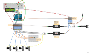
An RTC (Real-Time Clock) circuit and a display complete the physical part. Here is the schematic:
Now, the sketch. As I said it’s messy, probably buggy, and commented in Italian. But it woks. It is frequently changed, so I’ll try to keep it up to date.
The sketch needs four libraries. Three of them, Temperature Control Library, Time Library, OneWire Library are the usual found on the web. One of them, DS1307RTC, is slightly modified to add the handling of the sqw chip line (make the RTC led flash). If you would like to use the version on Github, simply delete the call to sqw in the sketch. I added a pull request for this change.
Compile the sketch, load it on Arduino and connect a console. You should some status messages. Press “h” and you should see a brief help about the commands available.
Without sending specific commands, the program irrigates in summertime and activates the heating system in the cold period.
In the cold period of the year, a daily program is used to determine the wanted temperature. This can be overridden with specific commands.
Similarly, for irrigation a predefined program is mostly used, but there are commands to override it: to suspend (in rainy days, for example), or to force a valve open etc.
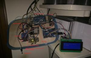
Here’s a photo of the circuit opened (which is the natural state for this type of object, IMO)


